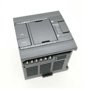
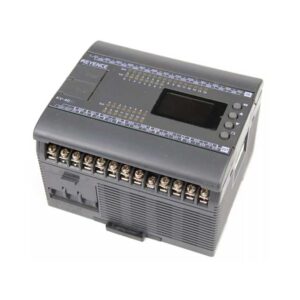
| KV-N14AR | Base Unit, AC power supply type, Input 8 points/output 6 points, relay output |
| KV-N14AT | Base Unit, AC power supply type, Input 8 points/output 6 points, transistor (sink) output |
| KV-N14ATP | Base Unit, AC power supply type, Input 8 points/output 6 points, transistor (source) output |
| KV-N14DR | Base Unit, DC power supply type, Input 8 points/output 6 points, relay output |
| KV-N14DT | Base Unit, DC power supply type, Input 8 points/output 6 points, transistor (sink) output |
| KV-N14DTP | Base Unit, DC power supply type, Input 8 points/output 6 points, transistor (source) output |
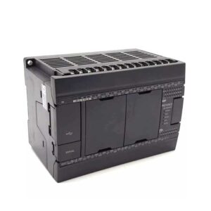
| KV-N24AR | Base Unit, AC power supply type, Input 14 points/output 10 points, relay output |
| KV-N24AT | Base Unit, AC power supply type, Input 14 points/output 10 points, transistor (sink) output |
| KV-N24ATP | Base Unit, AC power supply type, Input 14 points/output 10 points, transistor (source) output |
| KV-N24DR | Base Unit, DC power supply type, Input 14 points/output 10 points, relay output |
| KV-N24DT | Base Unit, DC power supply type, Input 14 points/output 10 points, transistor (sink) output |
| KV-N24DTP | Base Unit, DC power supply type, Input 14 points/output 10 points, transistor (source) output |
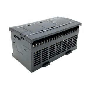
| KV-N40AR | Base Unit, AC power supply type, Input 24 points/output 16 points, relay output |
| KV-N40AT | Base Unit, AC power supply type, Input 24 points/output 16 points, transistor (sink) output |
| KV-N40ATP | Base Unit, AC power supply type, Input 24 points/output 16 points, transistor (source) output |
| KV-N40DR | Base Unit, DC power supply type, Input 24 points/output 16 points, relay output |
| KV-N40DT | Base Unit, DC power supply type, Input 24 points/output 16 points, transistor (sink) output |
| KV-N40DTP | Base Unit, DC power supply type, Input 24 points/output 16 points, transistor (source) output |
| KV-N60AR | Base Unit, AC power supply type, Input 36 points/output 24 points, relay output |
| KV-N60AT | Base Unit, AC power supply type, Input 36 points/output 24 points, transistor (sink) output |
| KV-N60ATP | Base Unit, AC power supply type, Input 36 points/output 24 points, transistor (source) output |
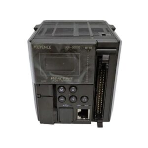
| KV-NC32T | Base unit 32-point type Input: 16 points, output: 16 points |
| I/O unit/Remote I/O unit | |
| KV-N16ER | Expansion output unit, output 16 points, relay output, screw terminal block |
| KV-N16ET | Expansion output unit output 16 points transistor (sink) output screw terminal block |
| KV-N16ETP | Expansion output unit output 16 points transistor (source) output screw terminal block |
| KV-N16EX | Expansion input unit Input 16 points 5/24 VDC switchable screw terminal block |
| KV-N8ER | Expansion output unit, output 8 points, relay output, screw terminal block |
| KV-N8ET | Expansion output unit output 8 points transistor (sink) output screw terminal block |
| KV-N8ETP | Expansion output unit output 8 points transistor (source) output screw terminal block |
| KV-N8EX | Expansion input unit DC input 8-point type switchable screw terminal block |
| KV-N8EXR | Expansion I/O unit,16-point type, Screw Terminal Block, Input 8 points, relay output 8 points |
| KV-N8EXT | Expansion I/O unit,16-point type, Screw Terminal Block, Input 8 points, transistor output 8 points |
| KV-NC16ET | Expansion output unit , output 16 points, transistor (sink)output, Connector type |
| KV-NC16ETE | Expansion output unit 16 outputs transistor (sink) output European terminal block |
| KV-NC16ETP | Expansion output unit , output 16 points, transistor (source)output, Connector type |
| KV-NC16ETPE | Expansion output unit 16 outputs transistor (source) output European terminal block |
| KV-NC16EX | Expansion Input Unit 16-input switching 5V/24V DC connector type |
| KV-NC16EXE | Expansion input unit 16 inputs European terminal block |
| KV-NC16EXT | Expansion I/O unit,32-point type,Connector type,Input 16 points,transistor output,16 points |
| KV-NC32ET | Expansion output unit , output 32 points, transistor (sink)output, Connector type |
| KV-NC32ETP | Expansion output unit , output 32 points, transistor (source)output, Connector type |
| KV-NC32EX | Expansion Input Unit 32-input switching 5V/24V DC connector type |
| KV-NC32EXT | Expansion I/O unit,Input 32 points/output 32 points, transistor (sink) output,Connector type, |
| KV-NC8ER | Expansion output unit , output 8 points, relay output, Connector type |
| Analog/Temperature unit/Remote I/O unit | |
| KV-N3AM | Analog I/O unit,Voltage/current input 2 channels + Voltage/current output 1 channel |
| KV-NC2DA | D/A conversion unit,2-point type |
| KV-NC4AD | A/D Conversion unit,4-point type |
| KV-NC4TP | Temperature input unit,input: 4 |
| Remote I/O unit | |
| KV-EP02 | EtherNet/IP® Compatible Communication Unit |
| Information/Network unit | |
| KV-N10L | Extension serial communication cassette RS-232C 1 port D-sub 9-pin |
| KV-N11L | Extension serial communication cassette RS-422A/RS-485 1 port European terminal block |
| KV-NC10L | Serial adapter RS-232C |
| KV-NC1EP | EtherNet/IP® unit |
| KV-NC20L | Serial adapter RS-232C/422A/485 |
| Power/Bus connection unit | |
| KV-N1 | Connection conversion unit For connector type unit connection |
| KV-NC1 | Connection conversion unit For terminal block type unit connection |
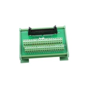
| Terminal block unit | |
| XC-H20-01 | Harness cable, MIL-MIL, 20 electrode, 1 m |
| XC-H20-03 | Harness cable, MIL-MIL, 20 electrode, 3 m |
| XC-H20-05 | Harness cable, MIL-MIL, 20 electrode, 5 m |
| XC-H20D-05 | Harness cable, MIL-loose lead cable, 20 electrode, 5 m |
| XC-H34-01 | Harness cable, MIL-MIL, 34 electrode, 1 m |
| Cable | |
| OP-42143 | CPU Direct Connection Cable 5-m (for KV-D30) |
| OP-87581 | Extension Cable for Extension Unit,DIN Rail Mounting(1m) |
| Memory card | |
| KV-M16G | SD memory card 16GB |
| KV-M1G | 1 GB SD Memory Card for KV-5000/KV-3000/KV-1000 |
| KV-M4G | SD memory card 4GB |
| Optional parts | |
| OP-35331 | USB cable |