| Product characteristics |
|---|
| Output signal | switching signal; analogue signal; IO-Link; (configurable) |
| Measuring range | | -1…1 bar | -1000…1000 mbar | -14.5…14.5 psi | -29.5…29.5 inHg | -401…401 inH2O | -100…100 kPa |
|
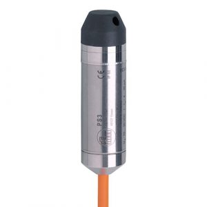
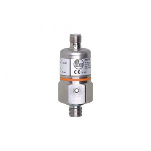
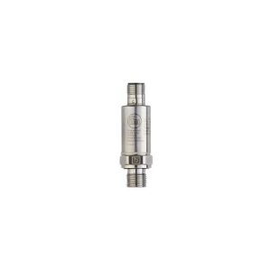
| Process connection | threaded connection G 1/4 internal thread (DIN EN ISO 1179-2) |
| Application |
|---|
| Special feature | Gold-plated contacts |
| Measuring element | ceramic-capacitive pressure measuring cell |
| Application | for industrial applications |
| Media | liquids and gases |
| Medium temperature [°C] | -25…80 |
| Min. bursting pressure | | 30000 mbar | 450 psi | 3000 kPa |
|
| Pressure rating | | 10000 mbar | 145 psi | 1000 kPa |
|
| Vacuum resistance [mbar] | -1000 |
| Type of pressure | relative pressure; vacuum |
| Electrical data |
|---|
| Operating voltage [V] | 18…30 DC; (according to EN 50178 SELV/PELV) |
| Current consumption [mA] | < 35 |
| Min. insulation resistance [MΩ] | 100; (500 V DC) |
| Protection class | III |
| Reverse polarity protection | yes |
| Power-on delay time [s] | 0.3 |
| Integrated watchdog | yes |
| Inputs / outputs |
|---|
| Number of inputs and outputs | Number of digital outputs: 2; Number of analogue outputs: 1 |
| Outputs |
|---|
| Total number of outputs | 2 |
| Output signal | switching signal; analogue signal; IO-Link; (configurable) |
| Electrical design | PNP/NPN |
| Number of digital outputs | 2 |
| Output function | normally open / normally closed; (parameterisable) |
| Max. voltage drop switching output DC [V] | 2 |
| Permanent current rating of switching output DC [mA] | 250 |
| Switching frequency DC [Hz] | < 500 |
| Number of analogue outputs | 1 |
| Analogue current output [mA] | 4…20; (scalable 1:5) |
| Max. load [Ω] | 500 |
| Analogue voltage output [V] | 0…10; (scalable 1:5) |
| Min. load resistance [Ω] | 2000 |
| Short-circuit protection | yes |
| Type of short-circuit protection | pulsed |
| Overload protection | yes |
| Measuring/setting range |
|---|
| Measuring range | | -1…1 bar | -1000…1000 mbar | -14.5…14.5 psi | -29.5…29.5 inHg | -401…401 inH2O | -100…100 kPa |
|
| Analogue start point | | -1000…600 mbar | -14.5…8.7 psi | -29.5…17.7 inHg | -402…240 inH2O | -100…60 kPa |
|
| Analogue end point | | -600…1000 mbar | -8.7…14.5 psi | -17.7…29.5 inHg | -240…402 inH2O | -60…100 kPa |
|
| Factory setting / CMPT = 2 |
|---|
| Set point SP | | -985…1000 mbar | -14.3…14.5 psi | -29.2…29.5 inHg | -396…402 inH2O | -98.5…100 kPa |
|
| Reset point rP | | -995…990 mbar | -14.45…14.4 psi | -29.4…29.3 inHg | -400…398 inH2O | -99.5…99 kPa |
|
| Min. difference between SP and rP | | 10 mbar | 0.15 psi | 0.3 inHg | 4 inH2O | 1 kPa |
|
| In steps of | | 5 mbar | 0.05 psi | 0.1 inHg | 2 inH2O | 0.5 kPa |
|
| Status_B High Resolution / CMPT = 3 |
|---|
| Set point SP | | -987…1000 mbar | -14.32…14.5 psi | -29.2…29.5 inHg | -396…401 inH2O | -98.7…100 kPa |
|
| Reset point rP | | -996…992 mbar | -14.44…14.38 psi | -29.4…29.3 inHg | -400…398 inH2O | -99.6…99.2 kPa |
|
| Min. difference between SP and rP | | 9 mbar | 0.12 psi | 0.3 inHg | 4 inH2O | 0.9 kPa |
|
| In steps of | | 1 mbar | 0.01 psi | 0.1 inHg | 1 inH2O | 0.1 kPa |
|
| Accuracy / deviations |
|---|
| Notes on the accuracy / deviation | switch point accuracy, linearity error under DNV GL: < ± 1%: < ± 1% |
| Switch point accuracy [% of the span] | < ± 0,4; (Turn down 1:1) |
| Repeatability [% of the span] | < ± 0,1; (with temperature fluctuations < 10 K; Turn down 1:1) |
| Characteristics deviation [% of the span] | < ± 0,25 (BFSL) / < ± 0,5 (LS); (Turn down 1:1; BFSL = Best Fit Straight Line; LS = limit value setting) |
| Hysteresis deviation [% of the span] | < ± 0,1; (Turn down 1:1) |
| Long-term stability [% of the span] | < ± 0,05; (Turn down 1:1; per 6 months) |
| Temperature coefficient zero point [% of the span / 10 K] | < ± 0,2; (-0…80 °C) |
| Temperature coefficient span [% of the span / 10 K] | < ± 0,2; (-0…80 °C) |
| Response times |
|---|
| Response time [ms] | < 1.5 |
| Delay time programmable dS, dr [s] | 0…50 |
| Damping for the switching output dAP [s] | 0…4 |
| Damping for the analogue output dAA [s] | 0…4 |
| Max. response time analogue output [ms] | 3 |
| Software / programming |
|---|
| Parameter setting options | hysteresis / window; normally open / normally closed; switch-on/switch-off delay; Damping; Display unit; current/voltage output |
| Interfaces |
|---|
| Communication interface | IO-Link |
| Transmission type | COM2 (38,4 kBaud) |
| IO-Link revision | 1.1 |
| SDCI standard | IEC 61131-9 |
| SIO mode | yes |
| Required master port type | A; (wenn PIN 2 nicht verbunden: B) |
| Supported DeviceIDs | | Type of operation | DeviceID | | Factory setting / CMPT = 2 | 467 | | Status_B High Resolution / CMPT = 3 | 983 |
|
| Note | | For further information please see the IODD PDF file under “Downloads” |
|
| Factory setting / CMPT = 2 |
|---|
| Profiles | Smart Sensor: Process Data Variable; Device Identification, Device Diagnosis |
| Min. process cycle time [ms] | 2.3 |
| IO-Link resolution pressure [mbar] | 1 |
| IO-Link process data (cyclical) | | function | bit length | | pressure | 14 | | binary switching information | 2 |
|
| IO-Link functions (acyclical) | application specific tag |
| Status_B High Resolution / CMPT = 3 |
|---|
| Profiles | Smart Sensor ED2: Digital Measuring Sensor (0x000A), Identification and Diagnosis (0x4000) |
| Min. process cycle time [ms] | 3 |
| IO-Link resolution pressure [mbar] | 1 |
| IO-Link process data (cyclical) | | function | bit length | | pressure | 14 | | device status | 4 | | binary switching information | 2 |
|
| IO-Link functions (acyclical) | application specific tag |
| Operating conditions |
|---|
| Ambient temperature [°C] | -25…80 |
| Storage temperature [°C] | -40…100 |
| Protection | IP 65; IP 67 |
| Mechanical data |
|---|
| Weight [g] | 235 |
| Materials | stainless steel (1.4404 / 316L); PBT+PC-GF30; PBT-GF20; PC |
| Materials (wetted parts) | stainless steel (1.4404 / 316L); Al2O3 (ceramics); FKM |
| Min. pressure cycles | 100 million |
| Tightening torque [Nm] | 25…35; (recommended tightening torque; depends on lubrication, seal and pressure rating) |
| Process connection | threaded connection G 1/4 internal thread (DIN EN ISO 1179-2) |
| Restrictor element integrated | no (can be retrofitted) |
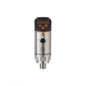
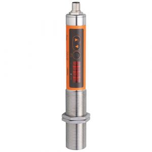
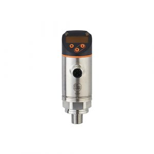
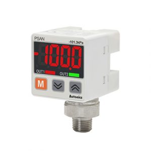
| Displays / operating elements |
|---|
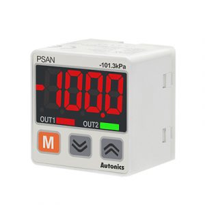
| Display | | Display unit | 5 x LED, green (mbar, psi, kPa, inH2O, inHg) | | switching status | 2 x LED, yellow | | measured values | alphanumeric display, red/green 4-digit |
|
| Remarks |
|---|
| Pack quantity | 1 pcs. |
| Electrical connection |
|---|
| Connection | Connector: 1 x M12; Contacts: gold-plated |