| Product characteristics |
|---|
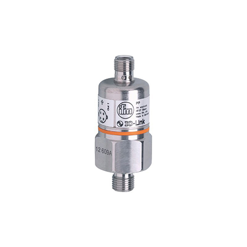
| Output signal | switching signal; IO-Link; (configurable) |
| Measuring range | | 0…100 bar | 0…1450 psi | 0…10 MPa |
|
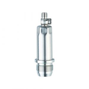
| Process connection | threaded connection G 1/4 external thread internal thread:M5 |
| Application |
|---|
| Application | for industrial applications |
| Media | liquids and gases |
| Conditionally suitable for | use in gases at pressures > 25 bar only on request |
| Medium temperature [°C] | -25…90 |
| Min. bursting pressure | |
| Pressure rating | |
| Type of pressure | relative pressure |
| Electrical data |
|---|
| Operating voltage [V] | 9.6…36 DC; (communication mode: 18…32) |
| Current consumption [mA] | < 45 |
| Min. insulation resistance [MΩ] | 100; (500 V DC) |
| Protection class | III |
| Reverse polarity protection | yes |
| Power-on delay time [s] | 0.3 |
| Inputs / outputs |
|---|
| Number of inputs and outputs | Number of digital outputs: 2 |
| Outputs |
|---|
| Total number of outputs | 2 |
| Output signal | switching signal; IO-Link; (configurable) |
| Electrical design | PNP |
| Number of digital outputs | 2 |
| Output function | normally open / normally closed; (parameterisable) |
| Max. voltage drop switching output DC [V] | 2 |
| Permanent current rating of switching output DC [mA] | 250 |
| Switching frequency DC [Hz] | 170 |
| Short-circuit protection | yes |
| Type of short-circuit protection | pulsed |
| Overload protection | yes |
| Measuring/setting range |
|---|
| Measuring range | | 0…100 bar | 0…1450 psi | 0…10 MPa |
|
| Set point SP | | 1…100 bar | 20…1450 psi | 0.1…10 MPa |
|
| Reset point rP | | 0.5…99.5 bar | 10…1440 psi | 0.05…9.95 MPa |
|
| In steps of | |
| Factory setting | | SP1 = 25.0 bar | rP1 = 23.0 bar | | SP2 = 75.0 bar | rP2 = 73.0 bar | | OUT1 = Hno | OUT2 = Hno |
|
| Accuracy / deviations |
|---|
| Switch point accuracy [% of the span] | < ± 0,5 |
| Repeatability [% of the span] | < ± 0,1; (with temperature fluctuations < 10 K) |
| Characteristics deviation [% of the span] | < ± 0,25 (BFSL) / < ± 0,5 (LS); (BFSL = Best Fit Straight Line; LS = limit value setting) |
| Hysteresis deviation [% of the span] | < ± 0,1 |
| Long-term stability [% of the span] | < ± 0,1; (per year) |
| Temperature coefficient zero point [% of the span / 10 K] | 0,2; (0…80 °C) |
| Temperature coefficient span [% of the span / 10 K] | 0,2; (0…80 °C) |
| Response times |
|---|
| Response time [ms] | < 3 |
| Damping for the switching output dAP in steps [s] | 0,003 – 0,006 – 0,010 – 0,017 – 0,060 – 0,125 – 0,250 – 0,500 |
| Interfaces |
|---|
| Communication interface | IO-Link |
| Transmission type | COM2 (38,4 kBaud) |
| IO-Link revision | 1.0 |
| Profiles | no profile |
| SIO mode | yes |
| Required master port type | A |
| Process data analogue | 1 |
| Process data binary | 2 |
| Min. process cycle time [ms] | 2.3 |
| Supported DeviceIDs | | Type of operation | DeviceID | | Default | 4 |
|
| Operating conditions |
|---|
| Ambient temperature [°C] | -25…85 |
| Storage temperature [°C] | -40…100 |
| Protection | IP 68; (7 days / 1 m water depth / 0.1 bar) |
| Mechanical data |
|---|
| Weight [g] | 226.65 |
| Materials | stainless steel (1.4301 / 304); FKM; EPDM/X; PA |
| Materials (wetted parts) | stainless steel (1.4305 / 303); ceramics; FKM |
| Min. pressure cycles | 100 million |
| Process connection | threaded connection G 1/4 external thread internal thread:M5 |
| Restrictor element integrated | no (can be retrofitted) |
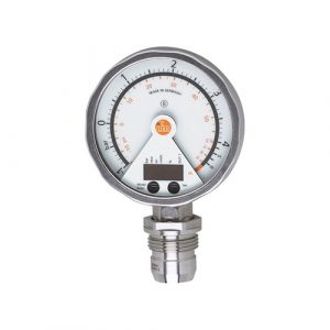
| Displays / operating elements |
|---|
| Display | | operation | 2 x LED, green | | switching status | 2 x LED, yellow |
|
| Teach function | yes |
| Remarks |
|---|
| Pack quantity | 1 pcs. |
| Electrical connection |
|---|
| Connection | Connector: 1 x M12 |