| Model | SV2-010L2 | |||
| General specifications | Capacity | 100 W | ||
| Input power supply | Voltage/frequency | Main circuit | 3-phase (or single phase) 200 to 240 VAC +10 to -15%, 50/60 Hz 270 to 324 VDC *1 | |
| Control circuit | Single-phase 200 to 240 VAC +10 to -15%, 50/60 Hz 270 to 324 VDC *1 | |||
| Allowable frequency fluctuation | Main circuit/control circuit | No more than ±5% | ||
| Overvoltage category | III | |||
| Control mode | Three-phase full-wave rectification, IGBT, PWM control, sine-wave current driving method | |||
| Feedback | 22-bit serial encoder (absolute) communication, fully closed control serial communication, analog feedback | |||
| Operating environment | Operating atmosphere | Enclosure rating | IP20 | |
| Pollution degree | Pollution degree: 2 (in an IP54 or higher control panel) However, usage under the following requirements required: • No corrosive gas or flammable gas present • No exposure to water, oil, or chemicals • No dust present | |||
| Operating ambient temperature | -5 to +60°C 23 to 140°F (no freezing; reduced ratings at +55°C 131°F or more) | |||
| Storage ambient temperature | -20 to +85°C -4 to +185°F (no freezing) | |||
| Operating/storage ambient temperature | 95% RH or less (no condensation) | |||
| Altitude | 2000 m 6561.7′ or less above sea level (usable at reduced ratings at 1000 m 3280.8′ or more) | |||
| Vibration resistance | 4.9 m/s2 16.1’/s2 (JIS C60068-2-6 compliant) | |||
| Impact resistance | 19.6 m/s2 64.3’/s2 ( JIS C60068-2-27 compliant) | |||
| Other | No static electricity noise, strong electric fields, magnetic fields, or radiation present | |||
| Min. insulation resistance | 500 VDC, 1 MΩ or more with insulation resistance tester | |||
| Applied standard | UL/CSA standards | UL61800-5-1, CSA22.2 No.274 | ||
| CE marking | Low-voltage directive | EN61800-5-1, EN50178 | ||
| EMI | EN55011 Class A, EN61800-3, EN61000-6-4 | |||
| EMS | EN61800-3, EN61000-6-2 | |||
| North America EMI standard | FCC Part15 B, ICES-003. Class A | |||
| Structure | Type | Attached to base mount | ||
| Safety function | STO function (STO/EN61800-5-2) | |||
| Safety function | Safety parameters | SIL3/EN61508, SIL CL 3/EN62061, PLe (Category3) / EN ISO13849-1: 2008 | ||
| Response time | 8 ms (max.) | |||
| Input | STO1, STO2: Base block signal for power module Internal impedance: 4.7 kΩ Operable voltage range: +24 V ±20% Max. delay time: 8 ms (Time from turning STO1, STO2 off until motor current cutoff) | |||
| Output | EDM: Built-in safety circuit status monitoring (fixed output) Max. allowable voltage: 30 VDC Max. allowable current: 50 mA DC Max. voltage drop at ON: 1.5 V Max. delay time: 8 ms (Time from changing STO1, STO2 until EDM change) | |||
| Applied standard | EN61800-5-2, EN ISO13849-1: 2008, EN61508, EN62061, EN60204-1, EN61326-3-1 | |||
| Protection function | Overcurrent, overvoltage, undervoltage, overload, regenerative abnormalities, etc. | |||
| Insulation withstand voltage | 1500 VAC or more (between primary side and ground) 3000 VAC or more (between primary side and secondary side) 350 VAC: Between secondary circuit and ground | |||
| Weight | Approx. 0.8 kg | |||
| Power supply/current capacity and power loss | Main circuit power supply | Three-phase 200 V/Single phase 200 V | ||
| Max. applicable motor capacity | 100 W | |||
| Power supply capacity for 1 amplifier | Three-phase 200 V: 0.3 kVA, Single phase 200 V: 0.3 kVA | |||
| Output current | Continuous | 0.91 Arms | ||
| Max. | 3.2 Arms | |||
| Main circuit power loss | 7.3 W | |||
| Regenerative resistor power loss | — | |||
| Control circuit power loss | 17 W | |||
| Total power loss | 24.3 W | |||
| Rated input current | Main circuit | Three-phase 200 V: 0.8 Arms, Single phase 200 V: 1.6 Arms | ||
| Control circuit | 0.2 Arms | |||
| Rush current | Main circuit | 34 A | ||
| Control circuit | ||||
| Performance specifications | Performance | Speed control range | 1:5000 (load torque ≤ rated torque conditions) | |
| Speed fluctuation rate | At load fluctuation | ±0.01% or less with load fluctuations of 0 to 100% (at rated rotation speed) | ||
| At main circuit voltage change | 0% with ±10% of rated voltage (at rated rotation speed) | |||
| At ambient temperature change | ±0.1% or less with ambient temperatures of 0 to +50°C 32 to 122°F (at rated rotation speed) | |||
| Torque control accuracy (reproducibility) | ±1% | |||
| Speed frequency response frequency | 2.6 kHz | |||
| Dynamic brake | Operated at main circuit power supply OFF, servo alarm, limit switch detection (LSP/LSN), forced stop detection (FSTOP) | |||
| Regenerative resistor | Built-in regenerative resistor: 50 W to 400 W … not installed 750 W to 5.0 kW … installed External regenerative resistor: OP-84399 (50 W to 1.0 kW) OP-87073 (1.5 kW *2) | |||
| Display Function | Panel function | 7-segment LED Rotary switch ×2 (16 ch) Slide switch ×1 (4 ch) | ||
| Status display LED | CHARGE: For notification of main circuit power supply input (orange) POWER: For notification of control circuit power supply input (green) CONNECT: For notification of connection (green) LINK1, LINK2: For notification of MECHATROLINK communication (green) | |||
| Auxiliary function | Gain control, alarm history, Z-phase search, etc. | |||
| I/O specifications | Sequence input signal | Number of inputs | 7 (3 high-speed input, 4 general input) | |
| Max. input voltage | 28.8 VDC | |||
| Rated input voltage | 24 VDC | |||
| Min. ON voltage | 19 VDC | |||
| Min. OFF current/voltage | High-speed input: 0.6 mA, general input: 0.3 mA | |||
| Common point mode | 7 points/1 common point (1 terminal) (bidirectional) | |||
| Input time constant | 250 μs, 500 μs, 1 ms, 2.5 ms, 5 ms, 10 ms | |||
| Input current | High-speed input: 4.5 mA, general input: 3.7 mA | |||
| Input impedance | Approx. 4.7 kΩ | |||
| Assignable input signals | Full signal assignment, logic-settable forced stop (FSTOP), external latch signals 1 to 3 (EXT1, EXT2, EXT3), origin return deceleration switch (DEC), forward limit switch (LSP), reverse limit switch (LSN), forward torque limit selection (PTL), reverse torque limit selection (NTL) | |||
| Sequence output signal | Number of outputs | 4 | ||
| Output mode | Transistor NPN output | |||
| Rated load | 30 VDC / 50 mA | |||
| Leakage current when OFF | 0.1 mA | |||
| Residual voltage when ON | 1.5 VDC or less | |||
| Common point mode | Independent common | |||
| Assignable output signals | Individual signal assignment excluding ALARM signal, logic-settable alarm (ALARM), in position (INPOS), speed matching (VCMP), zero speed detection (ZSP), operation preparation complete (RDY), torque limiting (TLM), speed limiting (VLM), electromagnetic brake timing (BRAKE), warning (WARN), Positioning proximity (NEAR) | |||
| Analog Feedback Input signal monitor | Max. input voltage | ±12 V | ||
| Accuracy | ±1% of F.S. | |||
| Resolution | ±10 bits | |||
| Input impedance | 30 kΩ | |||
| Encoder division pulse output signal | Output mode | Phase A (A+/A−), phase B(B+/B−), phase Z (Z+/Z−): Differential line-driver output | ||
| Line driver | SN75ALS174 (T.I.) or equivalent | |||
| Output frequency | 1.6 Mbps (with 2-phase, 4 times multiplication, 6.4 MHz or equivalent) *3 | |||
| Analog monitor output | No. of channels | 2 ch | ||
| Output range | ±10 V (linearity valid range ±8 V) | |||
| Resolution | 16 bits | |||
| Conversion precision | ±20 mV (typ.) | |||
| Max. allowable load current | ±10 mA | |||
| Conversion speed | 1.2 ms (typ.) | |||
| Communication specifications | MECHATROLINK-III communication | Communication protocol | MECHATROLINK-III | |
| Station address | 03H to EFH (Max. number of connectable slaves: 62) | |||
| Transmission speed | 100 Mbps | |||
| Transmission frequency | 125 μs, 250 μs, 500 μs, 750 μs, 1 to 4 ms (in multiples of 0.5 ms) | |||
| Communication cycle | Support for values starting at transmission frequency × 1 | |||
| Number of transmitted bytes | 32 bytes/station, 48 bytes/station (selectable with slide switch) | |||
| Transmission media/cable | Category 5e-compliant, STP cross cable | |||
| Operating specifications | Position control / speed control / torque control | |||
| Command input | MECHATROLINK-III command (sequence, motion, monitor, adjustment, etc.) | |||
| Max. transmission distance | 50 m 164.0′ *4 | |||
| USB communication | Connected device | PC | ||
| Communication standard | USB 2.0-compliant | |||
| Function | Status display, parameter setting, tuning, etc. | |||
| *1 When using a DC power supply input, set “*AC/DC power supply” to “DC”. *2 Use of 2 kW, 3 kW, and 5 kW servo amplifiers is possible depending on the operating conditions. *3 The division ratio can be set arbitrarily with a parameter. *4 For instances with 30 m 98.4′ or more, use ferrite cores (OP-84409) with 2 turn-winding. | ||||
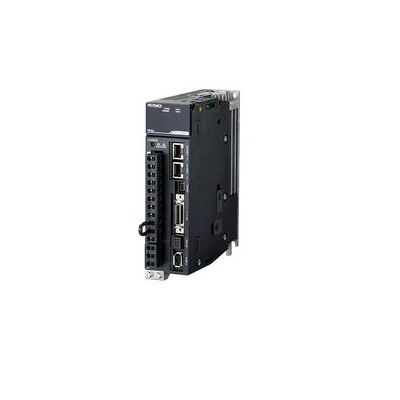
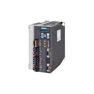
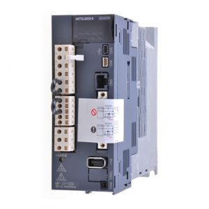
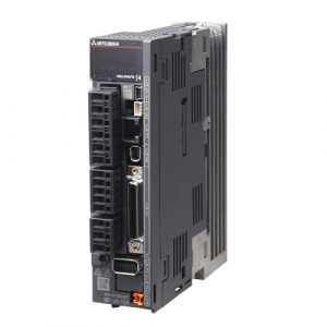
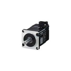
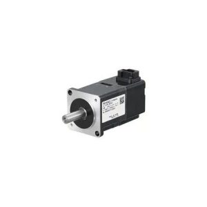
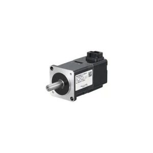
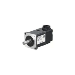
Bộ điều khiển Servo Keyence SV2-010L2 100W
Three-phase or single phase AC200 to 240V for 100W
SKU: SV2-010L2
Hãng sản xuất: Keyence
Chất lượng: Mới 100%
Bảo hành: Chính hãng
Chứng từ: CO/CQ, hóa đơn VAT

Thông tin bổ sung
| Thương hiệu | |
|---|---|
| Thời gian bảo hành | 1 Năm |
| Series |
